Menu
 0
/5
0
/5
.jpg)
The Mezzanine floor panel must be sufficiently strong to absorb all forces, distributed and point loads, whereby the floor should deflect only to a very limited extent. UNILIN has compiled indicative load tables as a support aid for architects or engineering offices.
The following parameters have been taken into account in compiling the load tables and influence the result.
Flooring type
Mezzanine P4, P5 or U7 (P6). U7 offers the maximum possible strength and stiffness.
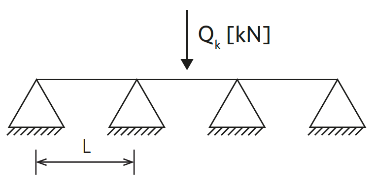
Spacing L (mm)
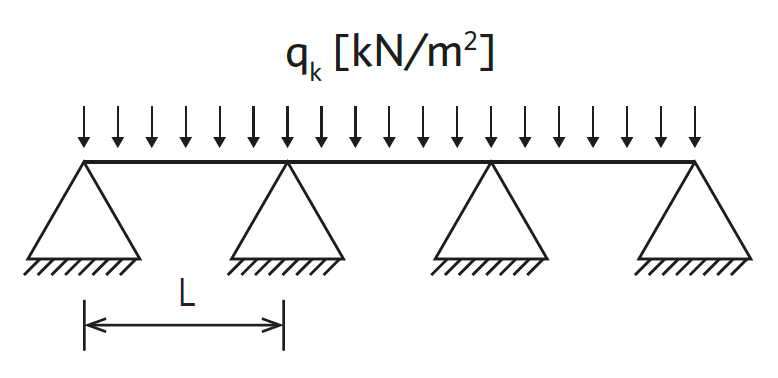
The greater the distance between the supports underneath the floor panel, the greater the deflection of the floor panel for the same load, or the lower the maximum possible load. Spacing that exceeds 1000 mm is not recommended.
Service class
A high air humidity reduces the strength and stiffness of the panels. Mezzanine P5 floor panels can be installed in humid conditions (service class 2). Mezzanine P4 and U7 are most suitable in dry conditions (service class 1).
Safety factor Ψ2
We recommend taking into account a safety factor of Ψ2 = 0.8 for storage areas in industrial environments. For storage areas in shops or meeting rooms, we apply a safety factor of Ψ2 = 0.6, for residential units or offices is 0,3 used.
Load duration
The longer a load is placed on the panels, the longer the panels are under stress and the more the panels will deflect.
Deflection criterion
In specifying the maximum loading, both strength criterion and permissible deflection are tested. The maximum deflection for distributed loads is max. L/250 or 6mm (Eurocode 5) and for point loads max. L/100 or 6 mm (EN 12871).
A uniform distributed load is a load distributed on the floor surface. The maximum distributed load is calculated using methods outlined in the Eurocodes and panel properties, determined in accordance with EN 789 and EN 1058.
Point loads are loads that are restricted to a concentrated area, such as the stamp of racks and wheels of transport pallets.
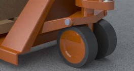
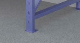
To determine the maximum point loads on Mezzanine floor panels, the panels are subjected to real-scale load testing in accordance with EN 1195.
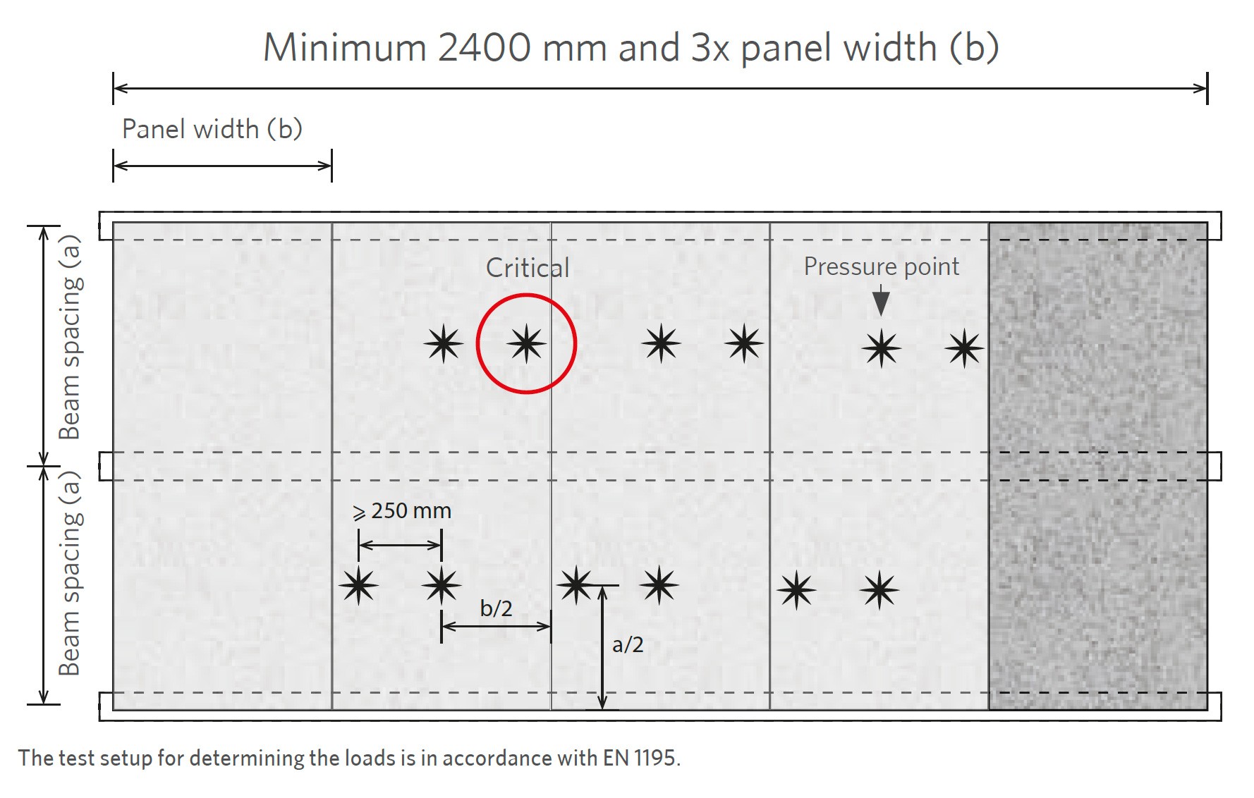
The floor panels are placed on supporting beams, whereby pressure points of 50mm x 50mm (![]() ) exert the point loads on the floor. The characteristic strength and stiffness of the floor is determined by 3 parameters.
) exert the point loads on the floor. The characteristic strength and stiffness of the floor is determined by 3 parameters.
Fmax,k
The characteristic load-bearing capacity in the ultimate limit state is converted to a maximum point load at which the floor panel experiences a fracture.
Fser,k
The characteristic load-bearing capacity in the service limit state determines the limit of the elastic region within which the maximum point load must remain.
Rmean
The average stiffness of the panel and the deflection criterion determine the maximum point load.
These three parameters are converted to a maximum point load for the Mezzanine floor in accordance with EN 12871, where the most critical value is retained as the maximum point load.
The load tables below indicate the maximum uniform distributed loads and point load for UNILIN Mezzanine floor panels. The following parameters are taken into account:
Uniform distributed load (UDL) |
Point load (PL) |
 |
 |
Maximum uniform distributed load qk (1 kN/m2 ≈ 100 kg/m2)
| Spacing L (mm) | |||||||||||
| 400 | 425 | 480 | 500 | 510 | 525 | 600 | 750 | 800 | 850 | 1000 | |
| U7 | 53.9 | 47.7 | 33.5 | 29.6 | 27.9 | 25.5 | 17 | 8.6 | 7 | 5.8 | 3.4 |
| P5 | 22.8 | 20.2 | 15.8 | 14.5 | 13.8 | 12.6 | 8.4 | 4.1 | 3.4 | 2.7 | 1.6 |
Maximum point load Qk (1 kN ≈ 100 kg)
| Spacing L (mm) | |||||||||||
| 400 | 425 | 480 | 500 | 510 | 525 | 600 | 750 | 800 | 850 | 1000 | |
| U7 | 5.8 | 5.7 | 5.6 | 5.5 | 5.5 | 5.4 | 5.2 | 4.5 | 3.7 | 3.2 | 1.8 |
| P5 | 2.9 | 2.9 | 2.8 | 2.8 | 2.8 | 2.7 | 2.7 | 2.3 | 1.9 | 1.7 | 1.1 |
Maximum uniform distributed load qk (1 kN/m2 ≈ 100 kg/m2)
| Spacing L (mm) | |||||||||||
| 400 | 425 | 480 | 500 | 510 | 525 | 600 | 750 | 800 | 850 | 1000 | |
| U7 | 67.3 | 56.0 | 38.8 | 34.3 | 32.3 | 29.6 | 19.7 | 9.9 | 8.1 | 6.7 | 4.0 |
| P5 | 34.3 | 29.2 | 20.2 | 17.8 | 16.8 | 15.3 | 10.2 | 5.0 | 4.1 | 3.3 | 1.9 |
Maximum point load Qk (1 kN ≈ 100 kg)
| Spacing L (mm) | |||||||||||
| 400 | 425 | 480 | 500 | 510 | 525 | 600 | 750 | 800 | 850 | 1000 | |
| U7 | 7.2 | 7.2 | 7.2 | 7.2 | 7.2 | 7.1 | 6.7 | 5.4 | 4.6 | 3.8 | 2.1 |
| P5 | 4.0 | 4.0 | 4.0 | 4.0 | 4.0 | 4.0 | 3.6 | 2.8 | 2.3 | 2.0 | 1.4 |
Maximum uniform distributed load qk (1 kN/m2 ≈ 100 kg/m2)
| Spacing L (mm) | |||||||||||
| 400 | 425 | 480 | 500 | 510 | 525 | 600 | 750 | 800 | 850 | 1000 | |
| U7 | 75.6 | 66.9 | 50.8 | 44.9 | 42.3 | 38.7 | 25.8 | 13.0 | 10.6 | 8.8 | 5.2 |
| P5 | 34.3 | 30.4 | 23.8 | 21.9 | 21.0 | 19.8 | 15.0 | 7.4 | 6.0 | 4.9 | 2.8 |
Maximum point load Qk (1 kN ≈ 100 kg)
| Spacing L (mm) | |||||||||||
| 400 | 425 | 480 | 500 | 510 | 525 | 600 | 750 | 800 | 850 | 1000 | |
| U7 | 8.1 | 8.0 | 7.8 | 7.7 | 7.7 | 7.6 | 7.2 | 6.6 | 5.3 | 4.6 | 2.7 |
| P5 | 4.4 | 40.3 | 4.2 | 4.1 | 4.1 | 4.1 | 4.0 | 3.8 | 3.3 | 3.0 | 2.0 |
The calculations and loading tables above have been compiled on the basis of the specified calculation methods and assumptions. The studies are provided merely for the purpose of information. UNILIN, division panels, its suppliers and the person who carried out the study accept no liability for information provided by these studies. The studies do not constitute a substitute of a complete stability study by an accredited engineering offices.